Experiment 1
LED lights
Introduction
We are all familiar with LED lights. They are all around us from household lights, flashlights, and indicator lights in a variety of electronic devices. In their most basic form they look like this:

LED is short for light-emitting diode and as with any electric light it produces light when electrical current flows through it. The Wikipedia article on them says “Electrons in the semiconductor recombine with electron holes, releasing energy in the form of photons” which sounds way cool (although I will admit I have no idea what an electron hole is).
In this experiment we are going to
- build a device that connects a single LED to the Arduino UNO.
- get our laptops set up so we can write programs throughout the course
- write our first program and upload it to the Arduino.
- after our success with getting a light to blink, we will work on a number of remixes.
Parts Needed
You will need the following parts:
- 1x LED (Choose any color)
- 1x 330Ω Resistor (the Ω is the symbol for ohm)
-
2x Jumper Wires (any color)

You will need a few more resistors and LEDs for the remixes later in the experiment.
Hardware Hookup
Resistors
As the parts list shows, you need a 330 ohm resistor. If you are lucky your resistors will initially be on a paper tape indicating the ohm value:
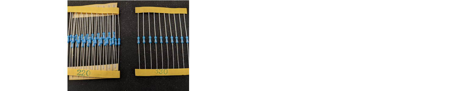
If you are very lucky your resistors will be loose and you will need to determine the value based on the colored bands. We will learn more about this later but if you look at the following image of the LED you will notice there are colored bands around the resistor.

The metalic color band should be on the right, and we read the colors from left to right. So in the above example, we have 5 bands and they are orange, orange, black, black, gold. As we will learn, that represents a 330Ω resistor. It is also common for resistors to have only 4 bands. In that scheme, a 330Ω resistor would be represented by orange, orange, brown, and some metalic color. Again, for you resistor geeks out there, we will get into more of the details later.
As you can see resistors come with beautifully straight wires, which are called legs. In order to fit the legs into the breadboard holes or sockets we have to bend those legs. We have the option to be sloppy and just sort of curve the wires around until they fit into the socket. The preferred, elegant, professional, way is to bend the legs into 90° angles in order to correctly fit the breadboard sockets.
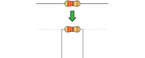
If you look online you will see tools that will help you bend the resistor legs perfectly. We don’t need that level of precision. Just do the best you can and get as close to 90° as possible without creating any stress in your life.
Resistors don’t have a right or wrong direction.
The LED
Pay close attention to the LED. They do have a right and wrong direction. The negative side of the LED is the short leg, marked with a flat edge.
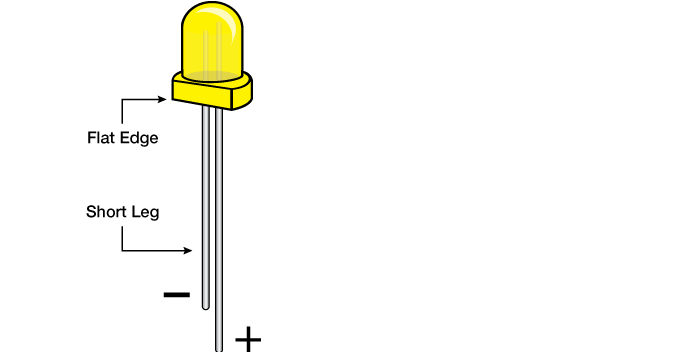
This is important
Remember, the short leg of the LED is negative and the longer leg positive!
Jumper wires
In a circuit, we are connecting components together. For example, we might want to connect the resistor to the LED and those components to the Arduino UNO. When we want to experiment with circuits, rather than permanently connect components, we use a breadboard in combination with jumper wires. Jumper wires are just wires with pin connectors on each end that can easily be placed in a breadboard socket and are used to connect two points together. It makes no difference what color wire you use. The convention is that black is associated with negative, or ground and that probably would be a good rule to follow. If your circuit has 3 LEDs, a red, green, and blue one it would be good to connect those to the Arduino using a red, green, and blue jumper wire, respectively. This conforms to Follow the Code, which we presented previously.
The circuit diagram
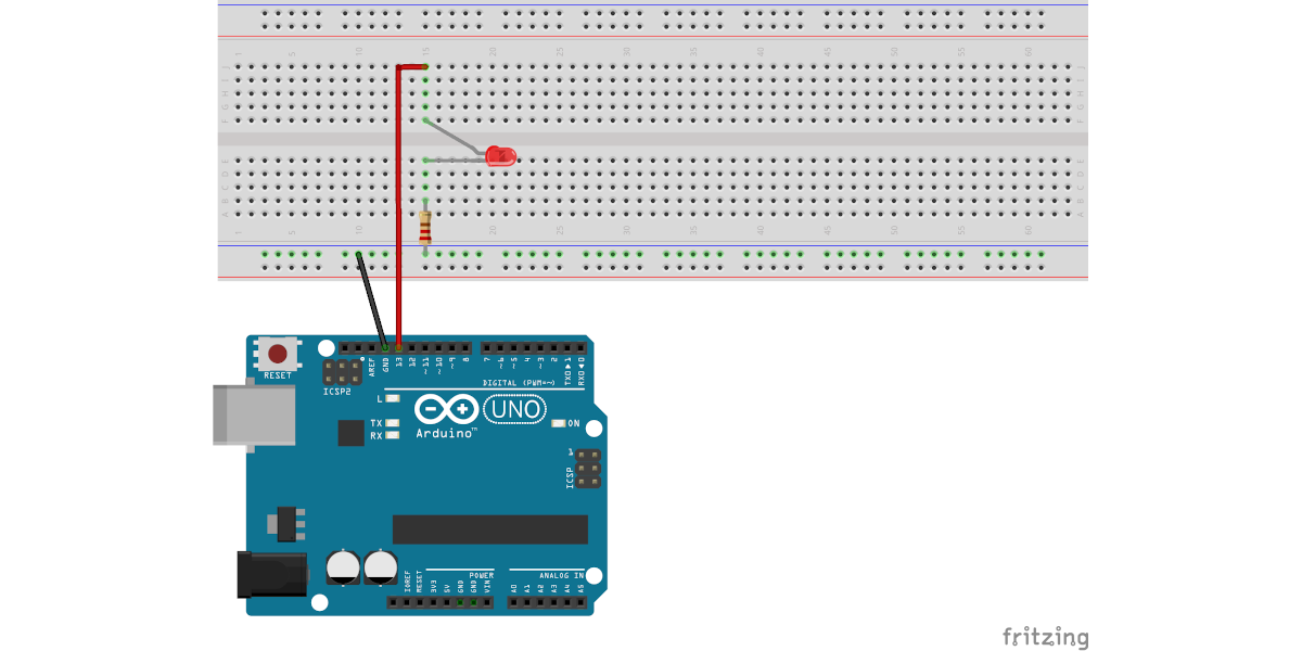
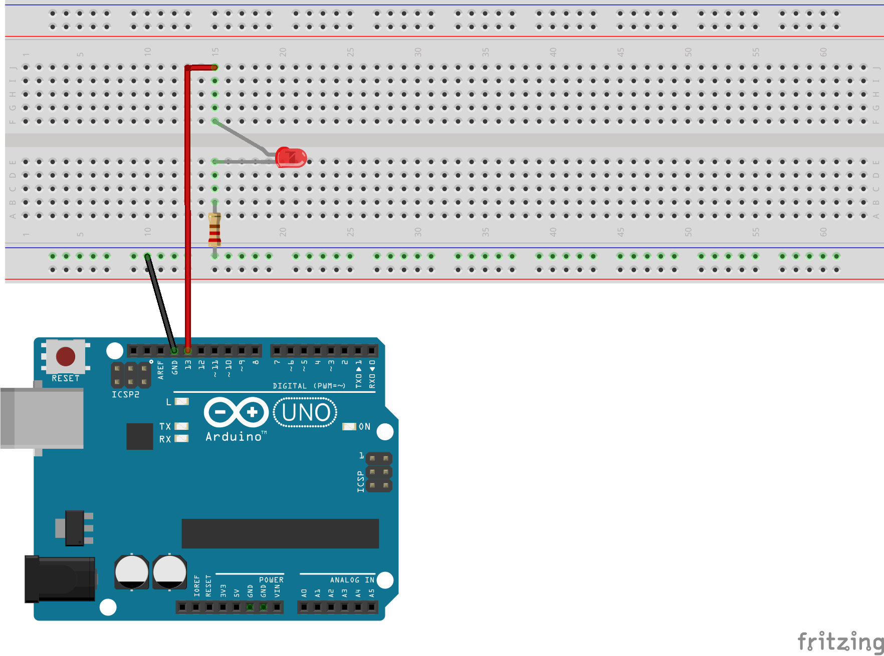
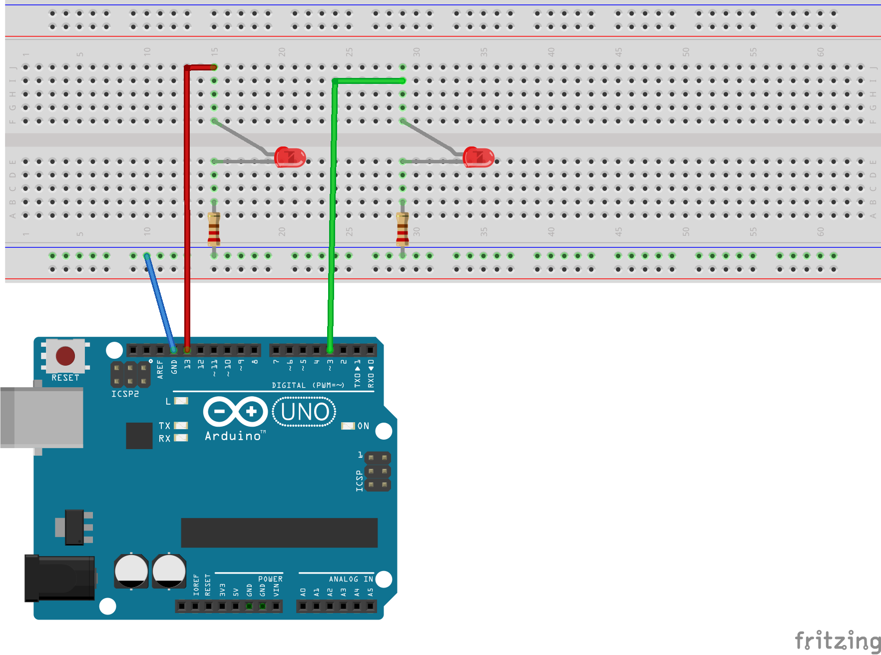
Each experiment will have an associated diagram, which shows how to connect the components to the breadboard and the Arduino Uno. The diagram for this experiment is below.
Having a hard time seeing the circuit? click here
Wondering why the word fritzing appears on the bottom right of the image? Fritzing is the software I use to draw electronic circuit diagrams, and it puts a fritzing watermark on each image.
Be sure the polarity on the LED is correct. The short leg of the LED is connected to the resistor which in turn is connected to GND (ground) of the Arduino Uno.
Installing the software
To program our devices we are going to use the Arduino IDE.
Integrated Development Environment
An IDE, or Integrated Development Environment, is a software program that helps people write computer code and converts that code to a software application. For example, to write an iPhone or Android app, developers use specific IDEs. The Arduino IDE we will use allows us to
- write computer code, much like a word processor
- convert that code to a form understandable to the Arduino Uno
- upload that converted code to the Uno.
Unfortuntely, the Arduino IDE is about 30 years behind the times. It looks like an application written in the 1990s and doesn’t have the features you would expect a modern program to have. That said, it does reliably work and it is free!
The Arduino website offers excellent instructions on how to install the software on your laptop:
Using those instructions, go ahead and install the Arduino IDE. Note that the installation instructions ask you for a donation but you have the option to select ‘just download’.
Write the program to blink the LED light.
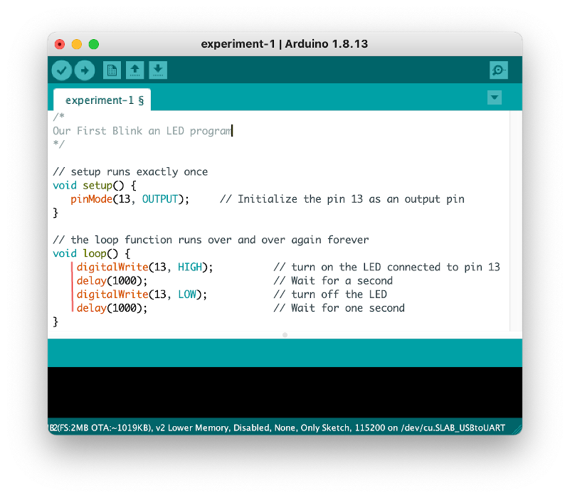
Open up the Arduino IDE (the program you just installed in the step above). Then, under the file menu select New and type in the following program
/*
Our First Blink an LED program
*/

// setup runs exactly once
void setup() {
   pinMode(13, OUTPUT);   // Initialize the pin 13 as an output pin
}

// the loop function runs over and over again forever
void loop() {
    digitalWrite(13, HIGH);      // turn on the LED
                                 // connected to pin 13
    delay(1000);                 // Wait for a second
    digitalWrite(13, LOW);       // turn off the LED
    delay(1000);                 // Wait for one second
}

What does that code mean?
Before we turn our attention to the code, let’s take a moment to look at the device we constructed. Instead of looking at this picture of my rendition, take a look at yours.
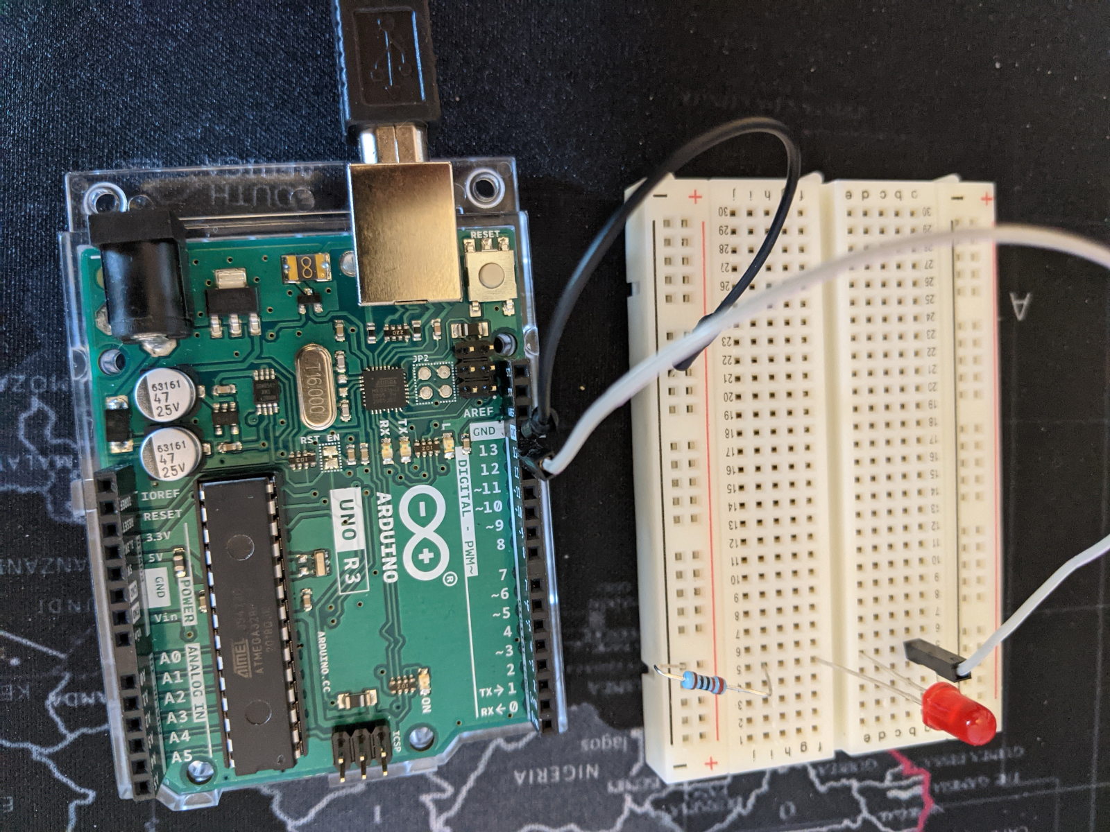
- You should see that the negative (shorter) leg of the LED is connected to the resistor which in turn is connected to ground (GND) of the Arduino.
- The long leg of the LED (positive) is connected to pin 13 of the Arduino.
Now to the code
Each Arduino programs requires at least two parts.
- the
void setuppart, which runs exactly once - the
void looppart, which runs repeatedly.
The setup part of the code above looks like this
    void setup() {
       pinMode(13, OUTPUT);   // Initialize the pin 13 as an output pin
    }
Informally, in English, you might think of void setup() as This is how you setup with the steps of setup enclosed in the braces. For example, if we had something like
   void greenCurryRecipe() {
       saute onions, ginger and garlic
       add broccoli and carrots and saute for 5 minutes
       add coconut milk
       ...
   }
we would read it in English as
This is how you greenCurryRecipe:
- saute onions, ginger, and garlic
- add broccoli and carrots and saute for 5 minutes
- add coconut milk
- …
Notice that the list of instructions is bounded by braces {} and we execute the steps one right after the other—i.e., sequentially.
In our Arduino code, setup consists of a single line:
pinMode(13, OUTPUT); // Initialize the pin 13 as an output pin
First, anytime the Arduino IDE running on your laptop detects the two characters // it interprets from there to the end of the line as a comment and is not sent to the Arduino Uno board. So // Initialize the pin 13 as an output pin is intended for us as a helpful comment. To the Arduino the following three lines are treated identically:
       pinMode(13, OUTPUT);   // Initialize the pin 13 as an output pin
       pinMode(13, OUTPUT);
       pinMode(13, OUTPUT);   // I think this is right
Again, these comments are helpful notes we make for ourselves and anyone else who needs to look at our code and are ignored when the code executes.
Immediately above the void setup in our code is
    /*
    Our First Blink an LED program
    */
This is another comment. Anything between /* and */ is a comment, which allows us to easily write multi-line comments such as
    /*
    My First Blink an LED program
    Emily Rice

    The LED is hooked up to pin 13

    */
On to the part of the setup that does execute:
pinMode(13, OUTPUT);
Recall that the circuit you constructed had your LED connected to pin 13 on the Arduino Uno. The pinMode line says to set that physical pin to be an output pin. OUTPUT pins perform some action in the world. In this case, the action is to turn on an LED light connected to pin 13. Another option for pinMode is INPUT. An input pin senses something about the world:
- was a button pressed?,
- did our motion sensor detect someone in the room?,
- did it sense water in the basement?
Now let’s move to the void loop
    // the loop function runs over and over again forever
    void loop() {
        digitalWrite(13, HIGH);      // turn on the LED
                                     // connected to pin 13
        delay(1000);                 // Wait for a second
        digitalWrite(13, LOW);       // turn off the LED
        delay(1000);                 // Wait for one second
    }
The loop consists of four lines. the first is
digitalWrite(13, HIGH); // turn on the LED
The part that does execute is
digitalWrite(13, HIGH);
As the helpful comment says, this turns on the LED connected to pin 13. HIGH means send 5 volts to whatever is connected to the pin, which in our case turns on the LED. LOW means send 0 volts to whatever is connected to the pin, which in our case turns off the LED.
The next line is
delay(1000); // Wait for a second
delay simply means to wait and do nothing. Within the parenthesis we say how long to wait in milliseconds (thousands of seconds). So we wait for 1 second.
The next line we turn off the LED and the line after that we wait 1 second. When we send the code to our Uno, the LED will blink one second on and one off.
Hopefully, that takes a bit of the mystery out of the code.
Bullet 1 of 10: Work to Code
We have already introduced the 10 bullets of the course that everyone should follow. Part of bullet 1, work to code, is that all lines within void setup and void loop need to be indented. In the code we wrote,
it is easy to see what the instructions are for loop. All those four lines are indented.
The following do not meet the requirement of work to code:
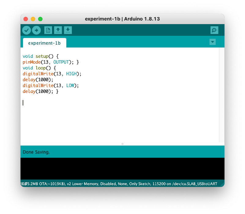
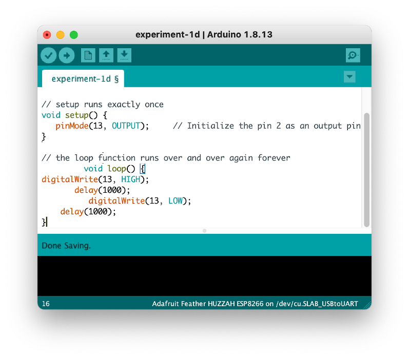
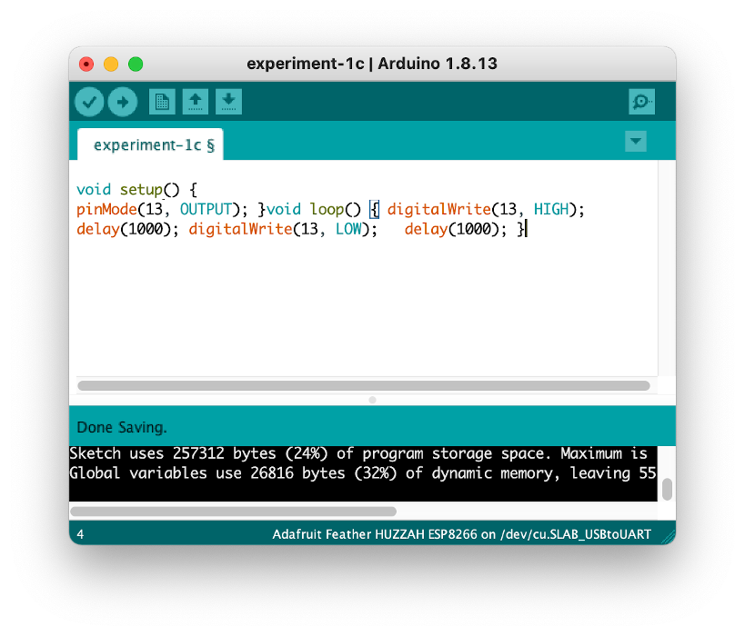
All have identical instructions and will work with the Arduino, but they are not as readable to humans. If you come back to your code a few weeks from now, you want to easily understand it. If you want to share your work with others so they can build upon it, you want your code readable.
This is the start of your work to code journey.
Bullet 5 of 10: Always be organized
Take the time to be organized and always be organized. By default, the Arduino IDE saves your code file as “sketch_today’s_date” in the general Arduino folder. If you are looking for the code that controlled the brightness of an LED light that you wrote 2 to 3 weeks ago and your 50 Arduino code files are labeled:
- sketch_dec03b
- sketch_dec03c
- sketch_dec04a
- sketch_dec04b
- sketch_dec07a
- sketch_dec07b
- sketch_dec07c
- sketch_dec07d
- sketch_dec08a
- …
You are going to have a hard time finding the correct file. If sometimes you save your file to the Arduino folder, sometimes to the desktop, and sometimes to the documents folder you are going to have a hard time finding the correct file.
Always be organized means having a directory for the class that is well-named. Have subdirectories for each set of projects, and give your files helpful names:
- oneLedBlinking
- twoLedsAlternating
- twoLedsWaltz
Always be organized also means having the directory automatically backed up to the cloud. There are a number of easy, free options including:
If your laptop dies, is stolen, catches on fire, or gets run over by a steam roller, having your work automatically backed up will be a relief.
The backup options are easy to setup and effortless to maintain.
I lost my work is not an option.
Go ahead and save your program in an organized way.
Back to coding …
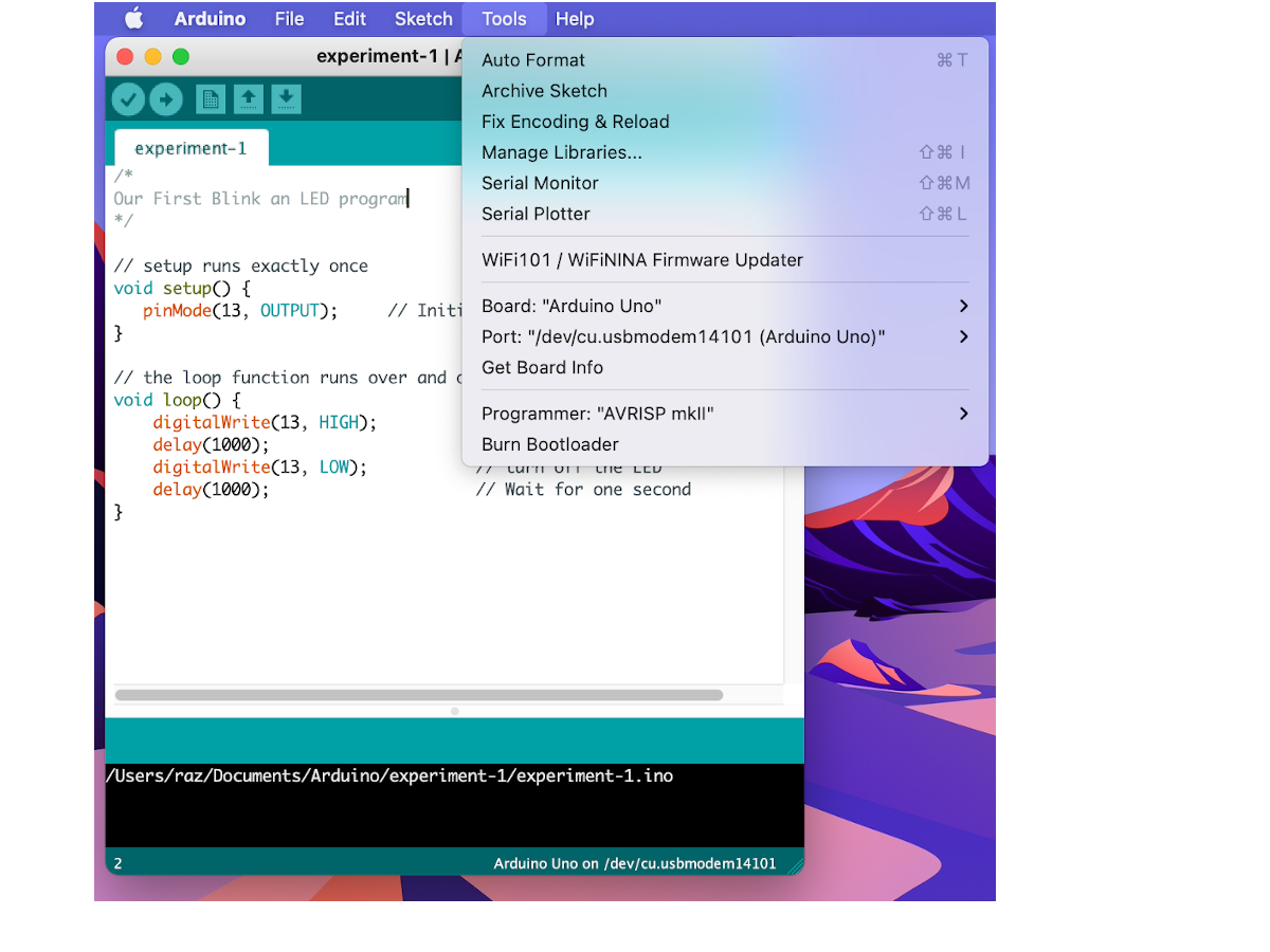
Now that we wrote and saved our code it is time to connect the Arduino Uno to our laptop if we haven’t done so already.
Then under the Tools menu under Board make sure Arduino Uno is selected and under port some port with the letters usb in them is also selected. If not, use the dropdown lists to select them.
Once that is done, check your program by clicking on the checkmark icon

The check is optional. It just checks your program for syntax errors. Next you can upload your program to your board by clicking on the arrow icon:

You now should have a blinking LED light.
Can you make the LED blink faster?
Two LEDs blinking
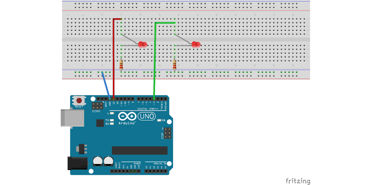
Now that we have one LED blinking, let’s get two blinking.
Once we know how to hook up one LED we pretty much know how to hook up several. The short leg of the LED (negative) is connected to a 330Ω resistor which in turn is connected to GND (ground) of the Arduino Uno. The long leg of the LED is connected to one of the Uno’s output pins, say pin 3:
And if we want the LEDs to blink at the same time our code would be…
/*
      Two LEDs blinking
*/

// setup runs exactly once
void setup() {
   pinMode(13, OUTPUT);
   pinMode(3, OUTPUT);
}

// the loop function runs over and over again forever
void loop() {
    digitalWrite(13, HIGH);
    digitalWrite(3, HIGH);
    delay(1000);
    digitalWrite(13, LOW);
    digitalWrite(3, LOW);
    delay(1000);
The remixes
Now it is your turn to experiment. Below are some short videos I made. Your task is to
Step 1 watch the video and analyze the pattern.
Step 2. Think before coding
Instead of directly implementing the pattern in the Arduino IDE, sketch out the pattern in your notebook. This is a crucial step. It allows your brain to pause, analyze, and convert what you see to something that can be implemented. For example, I might look at a video and sketch out in my notebook:
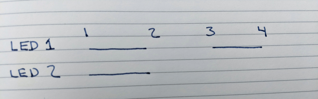
So here I think there are four beats in the pattern. My representation of an LED being on is a line and the representation of off is no line. So in this pattern both LEDs are on for the first beat and off for the second. Then the first led is on for the third beat and off for the fourth.
Then I write some psuedocode to align with that sketch…
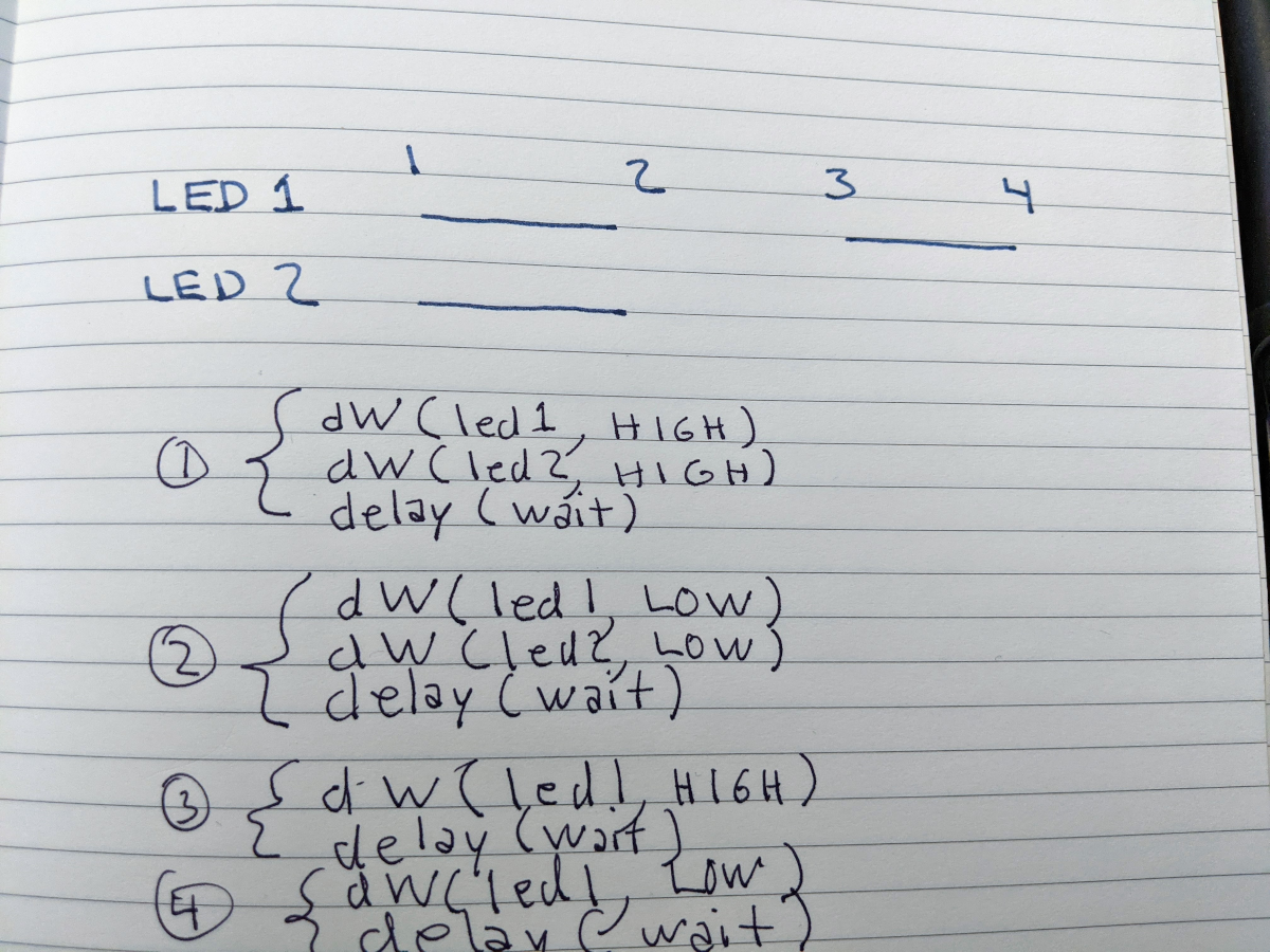
The dW is my shorthand for digitalWrite. Once I sketch the solution in my notebook I start coding. Your sketch can look different from mine. Maybe yours is more English like
- turn on led1
- turn on led2
- wait a beat
- …
There is nothing magical about my sketch notation. What is magical is sketching out a solution in your notebook before coding.
Every year I sit down with a group of instructors of advanced programming courses and the number one complaint is that students immediately start coding before actually thinking about the problem and sketching out a solution. (Maybe I shouldn’t have used used the word complaint since now you are thinking we sit around and gripe about students. Maybe I should have said our number one concern )
Step 3. Implement your code and test it
Using the sketch in your notebook as a guide, implement your solution in code, upload it to the Arduino Uno and see if it works.
Step 4. Debug.
When I write a program, I am amazed if it works the first time I try it. Sometimes I have a simple typo digitlaWrite instead of digitalWrite. Sometimes it is a simple logic error like typing digitalWrite(led, LOW) when I meant to turn on the led. And sometimes it is a gnarly logical problem. If you expect every program you write to run perfectly the first time you try it, you are going to be disappointed in this class. Expect bugs and mistakes.
It is like this with nearly everything in life.
If you are a beginner guitarist, you are going to make mistakes. If you have a passion for guitar, you will put up with fingers that don’t seem to cooperate and work through your mistakes. If you were forced to learn guitar those mistakes will seem unsurmountable. It is the same with soccer, ballet, skateboarding, yoga, and welding. (I only have personal experience with three of those)
Finally the remixes.
Can you write code that matches the following videos?
Remix 1: The Waltz
Remix 2: Double Tap
Remix 3: Slow n Fast
NOTE: In the video I erroneously call this double tap.
Remix 4: Cylon
1: Tutorials are CC BY-SA 4.0. Original page at Sparkfun Inventor’s Kit for Photon. This slight remix by Ron Zacharski